|
| INNOVATIONS |
|
TRANSFER 10 BIT PIXELS TO THE PCI BUS FOR $995 (US).
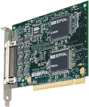
The PIXCI® D image transfer board receives 10 bit pixel
data from a KP-F100 or KP-F110 digital camera and, as a PCI bus
master, transfers it to the host computer's motherboard memory or
a PCI bus target. Imaging applications which were once restricted
to custom image processing hardware, or limited by expensive image
memory, can now be performed by the PIXCI® D board, EPIX
imaging software, a KP-F100 or 110 camera, a Pentium processor,
and a suitable PCI bus motherboard. The PIXCI® D maximizes
the use of the PCI bus to minimize the cost of interfacing the Hitachi
KP-F100 or KP-F110 digital camera to a computer.
IMAGE TRANSFER TO THE PCI BUS
The PIXCI® D uses the Hitachi KP-F100 or KP-F110 pixel
clock to register pixel data. It buffers the pixel data when the
PCI bus is busy and transfers buffered pixel data at rates up to
132 megabytes per second to the PCI bus. Pixel data may be transferred
to motherboard memory or to a PCI bus target.
VIDEO CAPTURE AND CAMERA CONTROL
The PIXCI® D has a programmable video window in which to
accept image data from the Hitachi KP-F100 or KP-F110 digital camera.
The video window can be as large as 1300 pixels by 1024 lines or
as small as 8 pixels by 8 lines. Camera control hardware and software
is provided for triggered capture and integration. Camera integration
can be programmed from 60 microseconds to 22 minutes.
VIDEO DISPLAY
Image display is provided by the host computer's video graphics
adapter (VGA) and monitor(s) or flat panel(s). Display resolution
is a function of the capabilities of these devices. Some Super VGA
(SVGA) monitors can display the full resolution of the camera image.
A software look-up-table feature allows display of 8 bits from the
10 bit gray level image.
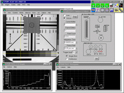
XCAP is a ready-to-run interactive image processing and analysis program for qualitative and quantitative image operations. A few mouse clicks select FFTs, histograms, morphology, measurements, edge detection, correlations, 3D plots, arithmetic operations, and many other functions. The tools provide analysis of the Hitachi KP-F100 or KP-F110 images using 10 bits of grey level per pixel. XCAP can control up to 8 PIXCI® D boards in a single computer.
XCOBJ programmer libraries include sample code for image processing and allow application-specific code to be added to the large selection of functions already developed. No royalties are required for software developed using XCOBJ libraries.
SOLUTIONS and SUPPORT
EPIX, Inc. has provided imaging solutions and support for OEM machine
vision manufacturers, camera manufacturers, radiologists, astronomers,
biologists, and engineers since 1984.
FEATURES
|
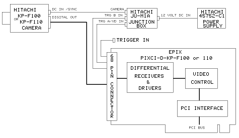
PIXCI® D Block Diagram and Cabling
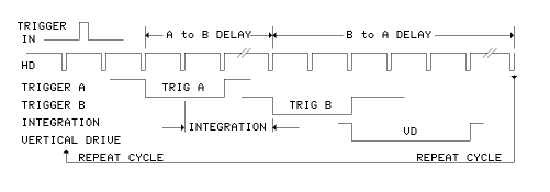
TRIGGER IN, A, and B Timing Diagram |
| The DIFFERENTIAL RECEIVERS & DRIVERS convert data from
differential to single ended TTL signals. Differential signals
are used to provide improved noise reduction over single ended
TTL signals.
The VIDEO CONTROL is used for image data formatting, video windowing, camera TRIGGER A and B control, trigger conditioning, and buffering of data from the differential receivers to the PCI interface. The VIDEO CONTROL provides the trigger controls and video format for the Hitachi KP-F100 or KP-F110. The PCI INTERFACE provides interrupt generation, PCI configuration registers, first-in and first-out buffers, and PCI bus master and target control. TRIGGER A, TRIGGER B, and TRIGGER IN signals are not required when the camera is operating in a continuous readout mode or if the the camera is triggered by external equipment. TRIGGER IN is an input to the PIXCI® D. TRIGGER A and B are outputs from the PIXCI® D to the camera via the junction box. TRIGGER IN is used when initiating a capture from an external signal. In response to the trigger, the PIXCI® D board controls the camera with TRIGGER A and B. TRIGGER A is used to capture an image with a shutter speed selected from the rear panel switches on the camera. TRIGGER A and B are used to capture an image with an exposure loaded by software. This mode of operation provides more precise control over the camera's integration time than is available with the rear panel switches on the camera. The integration time is programmed in increments of the horizontal time period of the camera. Integration times from one horizontal period to 22 minutes can be selected.
|
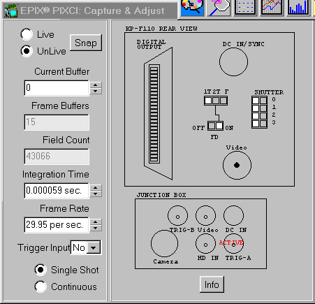 The XCAP Camera Control window automatically configures software
as "switches" are mouse clicked on the window, and
camera switches are moved on the KP-F100 or KP-F110. XCAP also
provides a Camera Settings window which lists camera switch
functions.
|
SPECIFICATIONS
| Resolution - KP-F100 Pixels: 8 to 1300 pixels per line. Lines: 8 to 1024 lines per image. Capture Window - KP-F100 Frame Rate - KP-F100 Resolution - KP-F110 Capture Window - KP-F110 Frame Rate - KP-F110 Bus Requirements
|
Connector
Signal Input and Output
REQUIREMENTS Display - XCAP
Display - XCOBJ
Motherboard
|


