PIXCI ® EB1miniF
Smallest Camera Link Frame Grabber Series
Applications
- Airborne
- Automotive
- Drone
- Industrial
- Mobile
- Rugged
- Underwater
Frame Grabber
- Base Configuration Camera Link
- MDR or SDR connector options
- Line Scan or Area Scan Cameras
- Supports more than 1000 different camera models
- Camera frame rate sequence capture
- Triggered image sequence capture
- Camera Integration & Async Reset Control
- LVTTL Trigger In and Strobe Out
- Industrial Temp Versions Available
Interface
- PCI Express Mini Card
- Full and Half Length versions
- 64-bit memory addressing
- Burst transfer at 250 megabytes per second
- 200 megabyte per second sustained data transfer
Software
- XCAP-Lite image capture, display, and save program included
- Capture video to computer memory with XCAP-LTD
- Stream video to disk with XCAP-STD
- XCLIB programmer libraries for frame grabber and camera control
- PXIPL image processing, measurement, and analysis libraries
- 3rd Party software available
- Windows & Linux, 32 & 64–bit
The PIXCI® EB1mini series of camera link frame grabbers use internal PCI Express Mini Card slots in small computer systems. Space constraints typically require routing of cables to a side of the case or to a nearby camera. Flexible cables are used to facilitate routing. The five versions of the PIXCI® EB1mini series provide multiple solutions for locating connectors.
VERSIONS
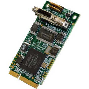 The
PIXCI® EB1mini frame grabber provides a vertical Camera Link SDR connector with FPGA on
a single printed circuit board using a full size mini card slot. At the maximum Camera Link clock rate of 85 MHz,
passive Camera Link cables up to 10 meters long can be used.
Dimensions:
Full mini circuit board: 50.95 x 30.0 mm (2.006 x 1.181 inches)
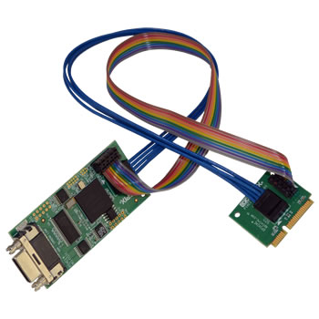 The
PIXCI® EB1miniH has an SDR Camera Link connector and FPGA on a separate circuit board
for mounting to the side of a small chassis. Two very flexible cables connect to a half length Mini card for the PCI
express connection. This allows for more mounting options in space constrained embedded systems that have half
length mini PCIe slots or full length slots that have a half length mounting standoff. At the maximum Camera Link
clock rate of 85 MHz, passive Camera Link cables up to 10 meters long can be used.
Dimensions:
FPGA circuit board: 66.04 x 30.0 mm (2.6 x 1.181 inches)
Half mini circuit board: 26.8 x 30.0 mm (1.055 x 1.181 inches)
Cable length between circuit boards shown: 30.48 mm (12 inches)
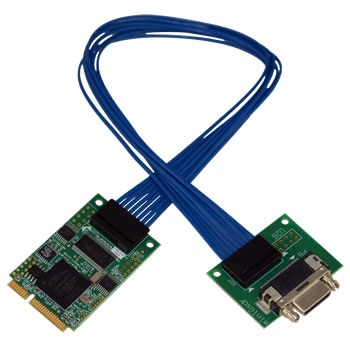 The
PIXCI® EB1miniG has the Camera Link connector on a separate circuit board and
connects to the FPGA circuit board with very flexible cables. This version requires less space on the panel for more
mounting options in space constrained embedded systems with a full size mini card PCIe slot. It is available with an
MDR or SDR Camera Link connector, and is shown here with an SDR. At the maximum Camera Link clock rate of 85
MHz, passive Camera Link cables up to 7 meters long can be used.
Dimensions:
Full mini circuit board: 50.95 x 30.0 mm (2.006 x 1.181 inches)
Connector circuit board: 38.354 x 30.0 mm (1.51 x 1.181 inches)
Cable length between circuit boards shown: 30.48 cm (12 inches)
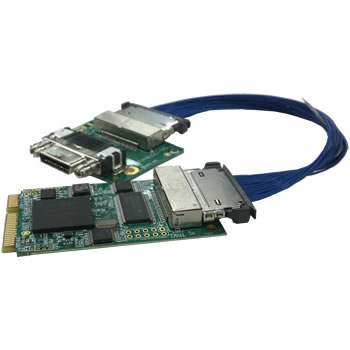 The
PIXCI® EB1miniGC has the Camera Link connector on a separate circuit board and
connects to the FPGA circuit board with very flexible cables and secure quick release connectors. Available with an
MDR or SDR Camera Link connector, and is shown here with an SDR. At the maximum Camera Link clock rate of 85
MHz, passive Camera Link cables up to 7 meters long can be used.
Dimensions:
Full mini circuit board: 50.95 x 30.0 mm (2.006 x 1.181 inches)
Connector circuit board: 38.354 x 30.0 mm (1.51 x 1.181 inches)
Cable length between circuit boards shown: 30.48 cm (6 inches)
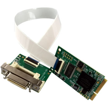 The
PIXCI® EB1miniGM has the Camera Link connector on a separate circuit board and
connects to the FPGA circuit board with flat Molex cables and low profile connectors. Available with an
MDR or SDR Camera Link connector, and is shown here with an SDR. At the maximum Camera Link clock rate of 85
MHz, passive Camera Link cables up to 7 meters long can be used.
Dimensions:
Full mini circuit board: 50.95 x 30.0 mm (2.006 x 1.181 inches)
Connector circuit board: 38.354 x 30.0 mm (1.51 x 1.181 inches)
Cable length between circuit boards shown: 30.48 cm (8 inches)
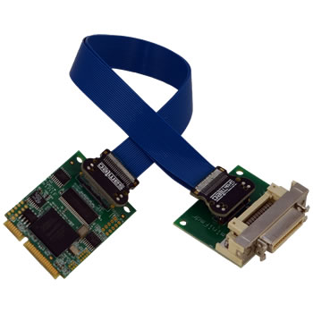 The
PIXCI® EB1miniF moves the Camera Link connector to a separate board and connects the
two with detachable
flat ribbon cable. This allows for more mounting options in space constrained embedded systems with a full
size
mini card PCIe slot. Available with an MDR or SDR Camera Link connector, shown here with MDR. At the maximum
Camera Link clock rate of 85 MHz, passive Camera Link cables up to 7 meters long can be used.
Dimensions:
Full mini circuit board: 50.95 x 30.0 mm (2.006 x 1.181 inches)
Connector circuit board: 38.354 x 30.0 mm (1.51 x 1.181 inches)
Cable length between circuit boards shown: 20.32 cm (8 inches)
OPTIONS
SDR camera plug with optional PoCL (Power over Camera Link)
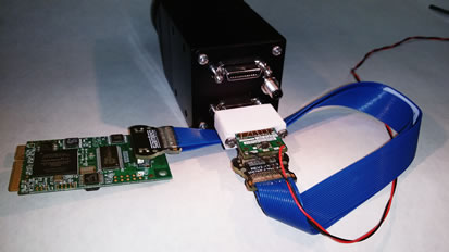 PIXCI® EB1miniF
with SDR camera plug on the end of the flat ribbon cable. Optional red and black wires power the PoCL
camera from the computer's 12 volt power supply.
EXAMPLE CONFIGURATIONS
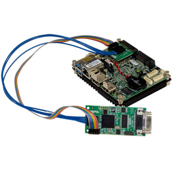 PIXCI® EB1miniH with MS-98H6 Motherboard
The PIXCI® EB1miniH base Camera Link frame grabber can be installed in either a Half Mini Card slot
or a
Full Mini Card slot with Half Mini Card standoff. This picture shows the PIXCI® EB1miniH with the
MS-98H6
Motherboard. The motherboard supports Pentium and Celeron processors and has a Half Mini PCIe slot for the
PIXCI
EB1miniH. The motherboard has a Pico-ITX form factor measuring 100 x 72mm.
The cables connecting the PIXCI EB1miniH frame grabber’s two circuit boards are 30.48cm or 12 inches long.
The
flexible cables allow the SDR Camera Link connector to be mounted almost anywhere on the computer chassis.
At
the maximum Camera Link clock rate of 85 MHz Camera Link cables up to 10 meters long can be used to connect
the
PIXCI EB1miniH to a base configuration Camera Link camera.
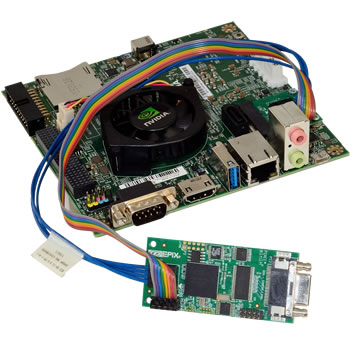 PIXCI® EB1miniH with NVIDIA Jetson TK1, TX1, or TX2
The PIXCI® EB1miniH base Camera Link frame grabber can be installed in the Half Mini Card slot on
the
NVIDIA Jetson TK1 developer kit.
Two PIXCI® EB1miniH base Camera Link frame grabbers can be interfaced to the NVIDIA Jetson TX1 or TX2 with a Connect Tech Elroy Carrier.
The XCLIB library for Linux now supports ARM-7 processors. Deliverables are binary driver blob with C wrappers, makefile, .a or .so library, .h files, examples, and manual. The binary driver blob with C wrappers supports all 3.x or 4.x Linux kernels and gives end-users maximum flexibility in choosing a Linux release for their product.
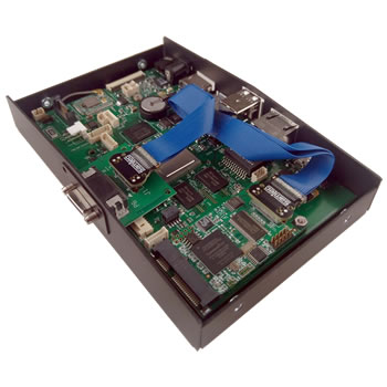 PIXCI® EB1miniF with Boundary Devices NITROGEN6_MAX
The PIXCI® EB1miniF base Camera Link frame grabber can be installed in the Full Mini Card slot on
the
Nitrogen6_MAX i.MX6 platform and fits inside
the optional enclosure.
The XCLIB library for Linux now supports ARM i.MX6 processors. Deliverables are binary driver blob with C wrappers, makefile, .a or .so library, .h files, examples, and manual. The binary driver blob with C wrappers supports all 3.x or 4.x Linux kernels and gives end-users maximum flexibility in choosing a Linux release for their product.
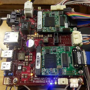 Dual PIXCI® EB1minis on a VersaLogic Condor
The
VersaLogic Condor supports two PIXCI® EB1mini frame
grabbers simultaniuosly recording video to disk in
a high-performance, compact form factor.
The Condor is a member of the VersaLogic "EPU" family of ultra-rugged embedded computers, designed to withstand extreme temperature, impact, and vibration.
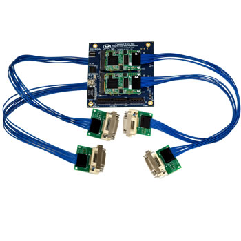 PIXCI® EB1minis with a PCIe/104 Quad Mini-PCIe Adapter
The
Connect
Tech Quad Mini-PCIe adapter mounts four PIXCI® EB1mini frame grabbers in a PCIe/104 embedded
system.
Any of the EB1mini frame grabbers can be installed in the top two slots.
The EB1miniH or EB1miniG can be installed in the bottom two slots. The Quad Adapter is pictured with the PIXCI® EB1miniG-M frame grabber with MDR Camera Link connectors.
SPECIFICATIONS
| Performance (Supports the camera's maximum): | Horizontal Resolution
Vertical Resolution Frame Rate Bit Depth |
| Signal Input & Output: | EIA RS-644 (LVDS) Drivers & Receivers
Pixel clock frequencies from 20 to 85 megahertz |
| Data Transfers: | Supports cameras with data output rates up to 250 megabytes per second
Burst data rates to Mini PCIe bus at 2.5 gigabits per second 64 bit memory addressing |
| Bus Requirement: | PCI Express Mini Card slot |
| Connectors: | One 26 pin 3M MDR (-M) or SDR (-S) camera link connector for base camera
10 pin header for Trigger, Frame Enable, Strobe, and General Purpose I/O |
| Power Requirements: | 3.3 volts at 150 milliamps
1.5 volts at 200 milliamps |
| Certifications: | CE Compliant
ROHS Compliant |
| EPIX Software Support: | Supported by XCAP-Lite (no charge with board purchase),
XCAP-Ltd, XCAP-Std,
XCLIB, and XCLIBIPL. |
